Knee replacement strategies over the past 50 years and the next 10 years.
This article provides an overview of knee replacement strategies over the past 50 years and some ideas about what might come.
Anatomic Referencing
Fig. 1: Anatomical Landmarks
From the 1970’s to the 1990’s, orthopedic surgeons predominately referenced the patient’s anatomy to determine the proper knee implant positioning. Dr. Hungerford championed one of these techniques, which became known as measured resection. Dr. Insall championed the other technique, which became known as classical alignment. Both techniques made implant positioning decisions based on the patient’s anatomy, as shown in Fig. 1. After the implant decisions were made, surgeons would perform ligament releases to balance the flexion and extension gaps.
Examples of anatomic landmarks that were used to determine implant positioning include:
Whiteside’s line
Posterior condylar Axis
Mechanical axis
Trans-epicondylar Axis
Medial third of the tibial tubercle
Intramedullary femoral canal
Medial and lateral malleolus
Using anatomic references works reasonably well for many patients, but outlier patients would often have condylar liftoff, paradoxical motion, and 20% dissatisfaction rates from an unbalanced knee.
Ligament Referencing
Fig. 2: Gap Balancing
In an effort to minimize ligament releases and make knee replacements feel more natural, surgeons measured ligament tension during surgery to help properly position implants. Initially, static, flexion and extension spacer blocks allowed surgeons to appreciate the ligament tightness after the femur and tibia cuts were made. These static spacer blocks provided a fixed distance, which represented the implant thickness, and the surgeon would subjectively estimate the ligament tension. Many surgeons wanted a fixed amount of tension and a variable distance, so dynamic gap tensioning devices were developed (Fig. 3-5). Determining the position of the femoral component relative to the tibial cut became known as gap balancing.
Fig. 3: Styrker’s early tensioning device
Fig. 4: Depuy’s early tensioning Device
Fig. 5: Depuy’s current tensioner
With gap balancing, surgeons usually made the distal femoral and proximal tibial bone cuts using anatomic landmarks like before. The overall coronal alignment of the leg was considered too important to rely on ligament tension. The surgeon would place a tensioning device in the flexed knee joint to set the flexion gap. The tensioning device would fully distract the knee joint with the knee at 90 degrees of flexion. The tensioning device would position the femoral component parallel to the tibial bone cut. In other words, the patient’s ligament tension determines the external rotation of the femoral component, not the patient’s bony anatomy. The posterior femur would be cut at a set distance from the tibial cut. The patient’s ligament tension in flexion determines the anterior-posterior translation of the femoral component, not the patient’s bony anatomy. When this flexion measurement was made with the manual tensioning device, the distal femoral cut had to be positioned at exactly 90 degrees relative to the tibial cut. This gap balancing technique balanced the flexion gap, not the extension gap.
Virtual Referencing
Fig. 6: Implants and bone displayed in digital environment
Virtual referencing is nearly synonymous with surgical navigation. Surgical navigation is the tool that digitally display implants and bony anatomy. Virtual referencing is the manipulation of implants and bones in a digital environment. Right now, virtual referencing requires surgical navigation, but future technologies like augmented reality or lidar might allow for virtual referencing without surgical navigation.
Virtual referencing is performed similarly to the manual tensioning devices described above. The surgeon makes a proximal tibial bone cut and inserts a tensioning device. Smith Nephew, Corin, and Depuy have developed robotic-specific tensioning devices (Figs. 5, 7, and 8) that utilize the navigation system to measure the distance between the femoral and tibial bones.
Fig. 7: Smith Nephew’s navigation compatible tensioning device
Fig. 8: Corin’s new digital tensioning device
Surgeons insert the tensioning device before the distal femoral bone is cut. The navigation system measures the extension and flexion gap, not the manual tensioning device. Some systems allow the surgeon to stress the ligaments through the entire range of motion, while others just stress the knee at ~5 degrees of flexion and ~90-100 degrees of flexion.
With virtual referencing, surgeons can manipulate the femoral component’s flexion/extension, varus/valgus, and multiple bony resection levels. Manipulating these variables allows the surgeon to properly position the femoral and tibial components, balance the flexion and extension gaps, and recreate the oblique joint line.
Virtual referencing has four distinct advantages over manual tensioning devices:
The virtual referencing user interface (UI) of current navigation systems displays 15 variables with high precision (0.5 mm):
medial and lateral distal femoral resection, medial and lateral posterior femoral resection, medial and lateral tibial resection, varus/valgus alignment of the femoral component, varus/valgus alignment of the tibial component, flexion/extension of the femoral component, internal and external rotation of femoral component, posterior tibial slope, medial and lateral extension gap distance with tensioning device, medial and lateral flexion gap distance with tensioning device.
Changing one variable has downstream consequences for the other variables, which can be easily visualized and analyzed with virtual referencing before committing to the final bone cuts.
The virtual referencing can compute the distance between the tibial and femoral implants in a multitude of knee positions (0 to 120 degrees). The manual tensioning devices in Figs. 3–4 are only accurate when the distal femoral bone cut is positioned exactly 90 degrees from the tibial bone cut.
The navigation system allows the surgeon to manipulate the femoral component’s flexion/extension, varus/valgus, and resection level, which gives the surgeon more flexibility in balancing the extension and flexion gaps. Manual tensioning devices only balance the flexion gap.
Positioning the femoral implant as it relates to the tibial component (relational positioning) is currently possible with virtual referencing in partial knee replacements. The red dots on the femoral component represent the tibial component’s surface relative to the femoral component (Fig. 9). With a partial knee replacement, surgeons have more flexibility in the femoral component positioning than the tibial component; hence, the red dots are displayed on the femoral component. This calculation is relatively simple since the tibial poly is flat in the coronal and sagittal planes. The poly in a total knee replacement is curved in the coronal and sagittal planes, which could complicate the calculations.
Fig. 9: Tibial contact points displayed on the partial femoral component.
Virtual Referencing in the near future
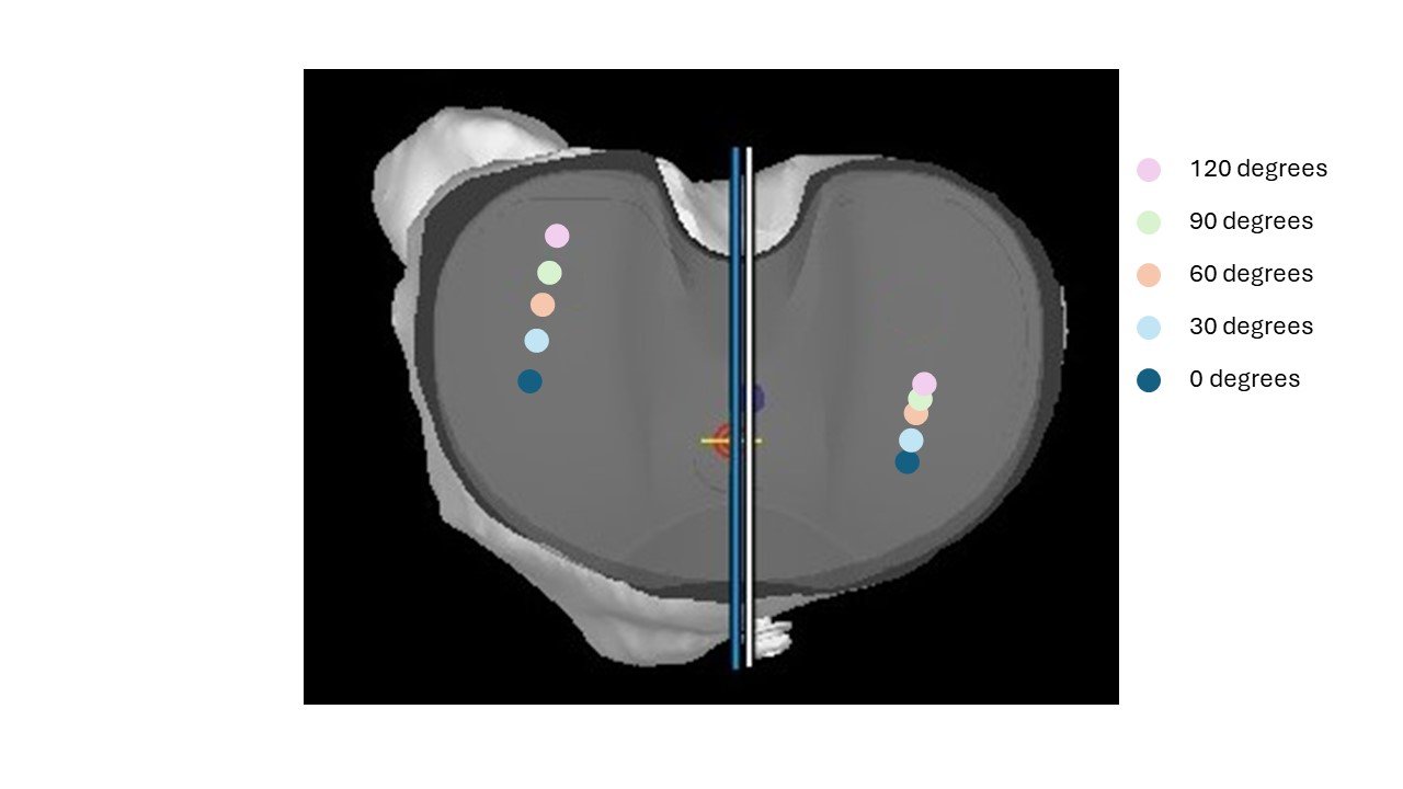
Surgeons will want to position the tibial component in a total knee relative to the femoral component (relational positioning). Since the surgeon can still manipulate the tibial component more freely than the femoral component during the trialing of the knee replacement surgery, the femoral component contact points should be displayed on the tibial component (Fig. 10-12). Fig. 10 shows the ideal contact points. Fig. 11 shows the contact points on the tibia where the tibial component needs to be externally rotated more. Fig. 12 shows the contact points on the tibia where the tibial component needs to be lateralized and/or the femoral component medialized.
Fig. 10: Ideal femoral contact points on tibial implant
Fig. 11: Femoral contact points on internally rotated tibial component
Fig. 12: Femoral contact points on medialized tibial component
Currently, I check the rotational position of the tibial and femoral components (relational positioning) at the beginning and end of the case (Fig. 13). Many navigation systems will display the internal or external rotation of the tibia axis relative to the femoral axis, so I record these measurements at the beginning of the case at ~5 degrees of flexion and 90 degrees of flexion. At the end of the case, I try to float the trial tibial component to recreate these same rotation numbers.
Fig. 13: Top-down view of femoral component on tibial component (femur in red, tibia in yellow)
The current navigation systems do not measure these 4 variables:
Femoral component medial/lateral translation
Tibial component medial/lateral translation
Tibial component anterior/posterior translation
Tibial component internal/external rotation
Virtually displaying the femoral component contact point on the tibial component can provide the surgeon with the information they need to accurately measure and execute on these 4 variables.


